This techtip describes, shows photographs and provides references for the four types of AC loaders for the B-Series, Soveriegn, Landlord, 700, and 725 Tractors (between 1957 to 1971).
Differences in the four loader Frames and Mounts
There were four types of loaders used on these tractors:
1) L10 first type
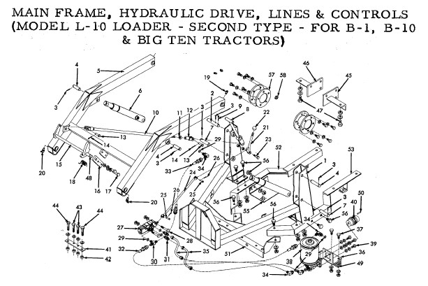
2) L10 second type
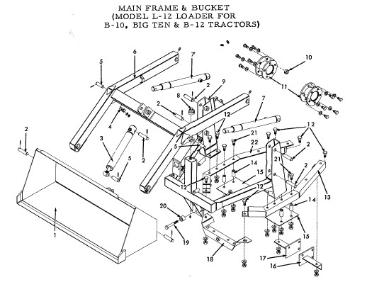
3) L12
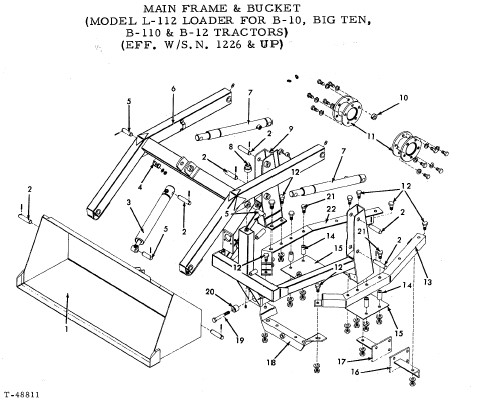
4) L112
Note: The Simplicity model numbers 990412 and 990515 corresponded to the L12 and L112 loaders. The Simplicity loaders had two kits for the 10hp and 12hp machines, Kit 510 and Kit 512 respectively.
The Dealers Parts Catalog lists all the parts for these loaders and can be found at the corporate Simplicity site:
http://www.simplicitytechpubs.com/6767PRINT/PDF_files/TP_400_3775_00_XX_A.pdf
The sketches of the four different loaders are shown in the five pictures below. There are two different sketches of the L112 which differ by the rear mounting brackets. The round bar mounting bracket in the last sketch is used on the longer frame B-Series tractors.
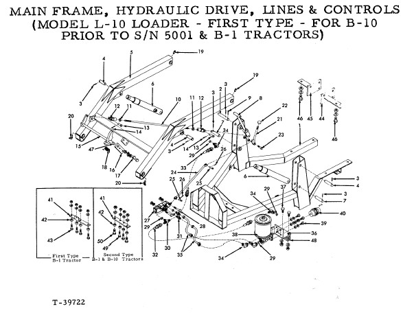
Differences between the L10 1st type and the rest of the loaders:
1. The Rear Mounting Brackets on the early L10 1st type loader are approximately 1/4" longer, otherwise same bolt pattern.
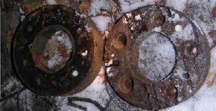
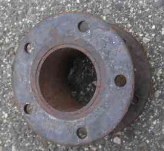
2. The Rear wheel spacers for the L10 1st type was a round disk of steel and the L10 2nd type, L12 and L112 used a pipe with two flanges.
3. The L10 first type loader is the only loader out of these four which can not be removed from the subframe.
4. The L12 & L112 42" buckets are 10" wider than both of the L10 loaders 32" bucket.
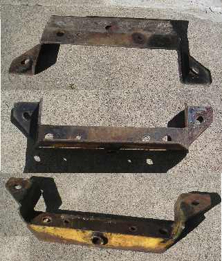
Differences between the L10 Loader 2nd type and the rest:
1. The L10 2nd type rear frame looks to flow the tractor straight back while the L12/L112 angles back to the rear mount. The following blow up of the L10 2nd type shows the difference in the L10 2nd type:
2. Again, the L12 & L112 42" buckets are 10" wider than both of the L10 loaders 32" bucket.
Wheel Spacer Kit for 10 first type:
This section shows wheel spaceres used on the L10 first type loader.
1st Type L10 spacer:
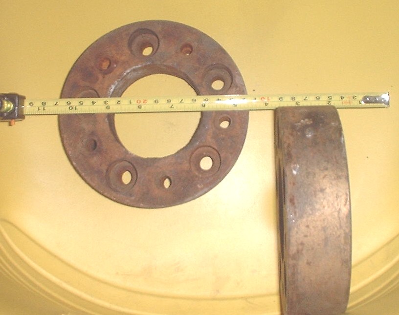
1st Type L10 spacer (showing the dimensions):
Wheel Spacer Kit (PN: 841012):
This kit was used on the L10 2nd type,L12, & L112 loaders. The original wheel spacer kit 841012 went for $19.35 in 1968 (see 990412 manual on the Simplicity site for more information on this).
2nd type L10/L12/L112 Wheel Spacer and the spacers which allow for the tractor control bolt area:
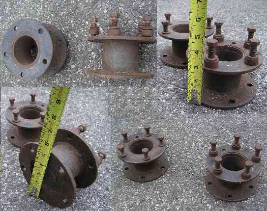
2nd type L10/L12/L112 Wheel Spacer (looking down at it so you can see the holes do not line up):
L10 1st Type Mounting:
This section lists the various parts needed to mount the L10 first type loader to a B-Series Tractor.
The following major parts are needed:
1. Front Bracket (two types one for B1 and one for B10)
2. LH & RH Rear Mounting Brackets
3. Wheel Spacer
4. Counter Weight Box
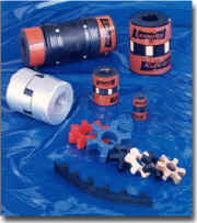
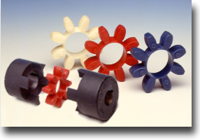
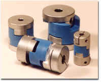
5. LoveJoy pump to engine connector
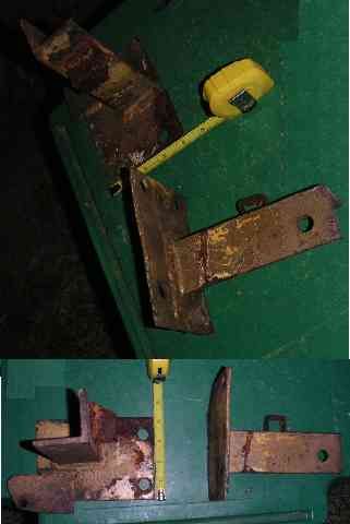
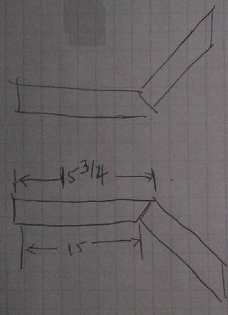
Below are some measurements of the L10 1st type loader LH & RH Rear Mounting Brackets: 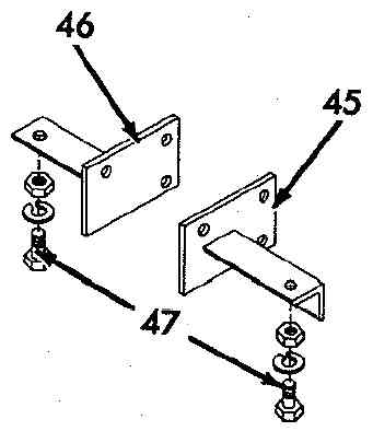
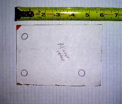
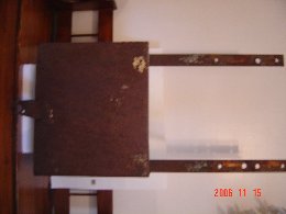
Here's a cardboard cutout of the plate used on the left rear mount plate (#44 Bracket Rear L.H. 2016877). The left mount and right mount look to be mirror images of each (#45 Bracket Rear R.H. 2016878). This plate is a 4" x 6" wide flat piece of steel which has a 6" long 2"x2" angle iron welded to it.
These are the rear mounts showing perspective and measurements:
The LoveJoy connects the pump to the engine. More information can be found at this post regarding discussions on the LoveJoy parts:
http://www.simpletractors.com/club2/topic.asp?ARCHIVE=true&TOPIC_ID=26911
http://www.lovejoy-inc.com/
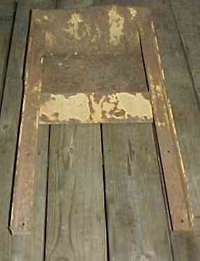
Sketches below are of the L10 1st type counter weight box along with measurements:
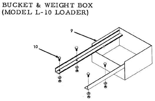
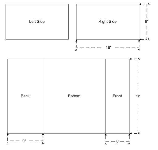
Sketch of unfolded sheet metal of box:
Sketch of complete box:
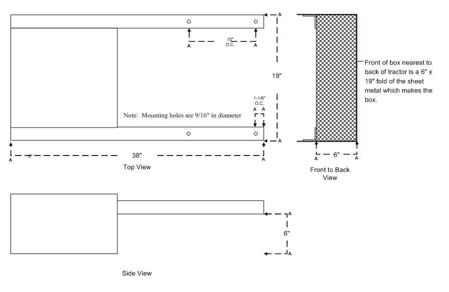
Box looking straight down (Right side up):
Box upside down:
Box right side:
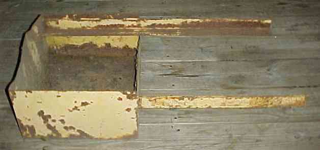
Box looking front to back:
L10 1st Type Loader Assembly Measurements:
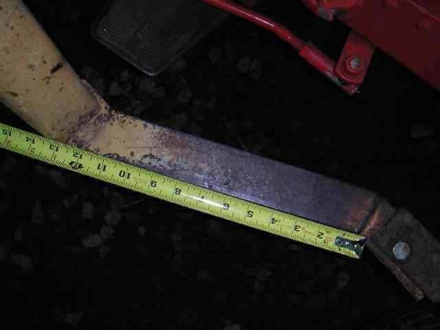
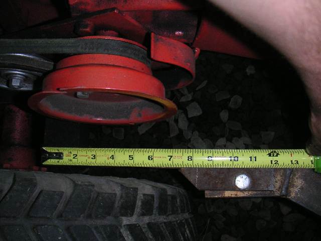
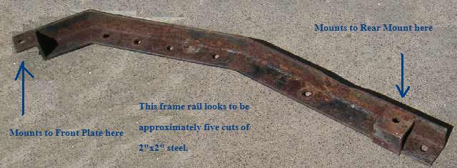
This is a measure of the last section of the rear frame rails (where capscrew #46 joins the mount) looking down this is made of a 2"x2" piece of angle iron:
This is a measure of the mid section of the rear frame rail (looks to be about 12"):
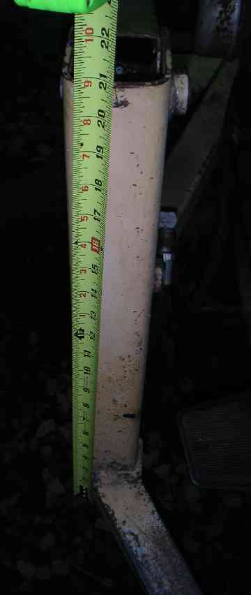
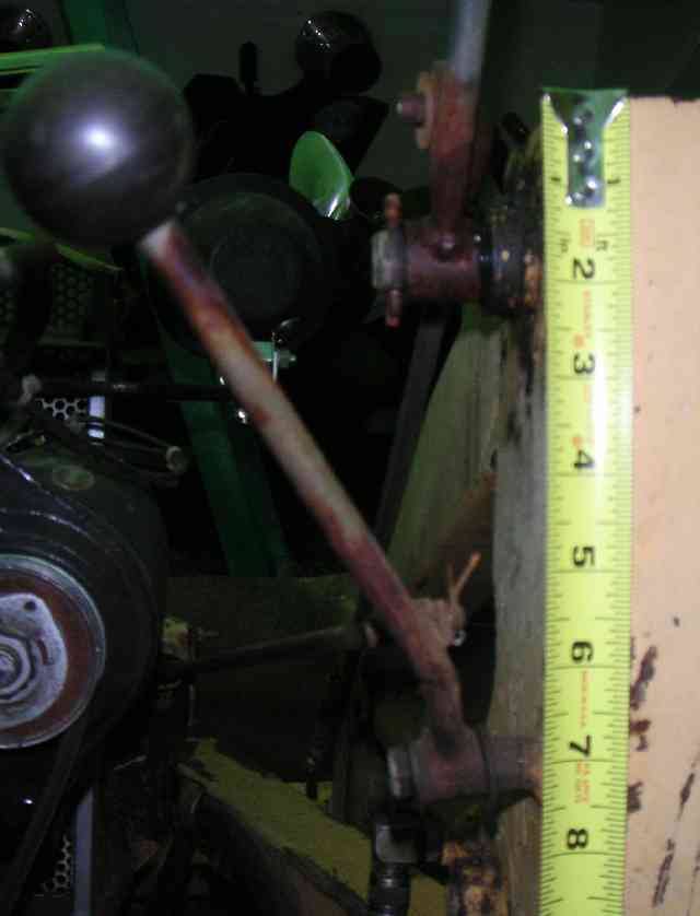
L10 Left Side Tower Height (shade under 21"):
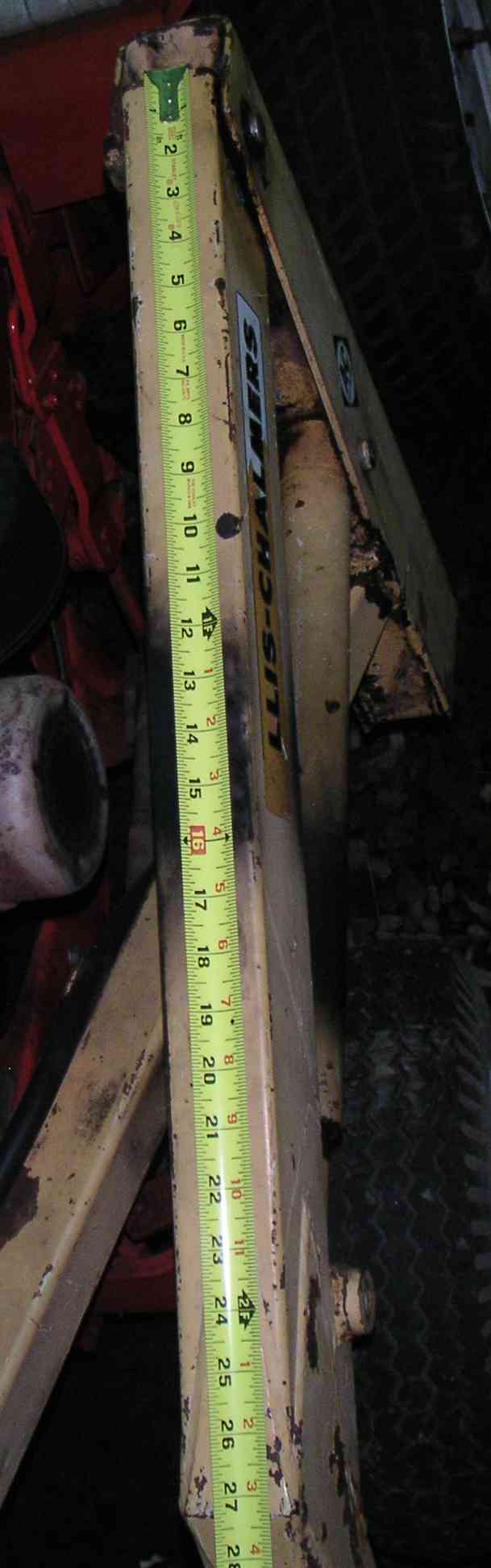
L10 Arm Length (left side, shade over 27-1/4"):
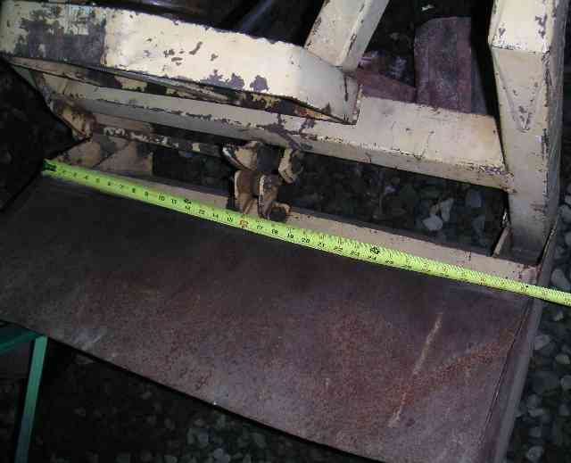
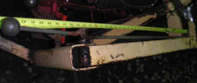
L10 Bucket width (slightly larger than 32" wide):
L10 Control Placement (right side):
L10 Trip Arm Length (right side, approximately 34/35"):
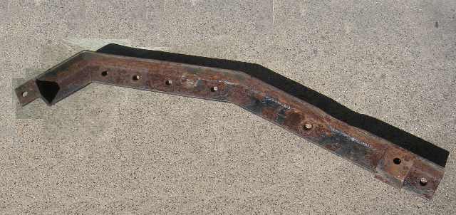
This loader frame was cut when the restoration was performed, they may not have known about or had the spacers:
Poor modification hugs the wheel/tire too closely:
Shows how far back approximately needed to extend frame to repair:
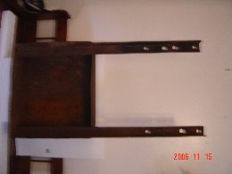
Left side mount point of the L10 loader:
Rear frame section of Loader Assembly:
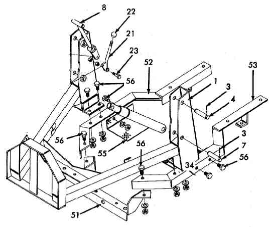
SubFrame for the L10 2nd type:
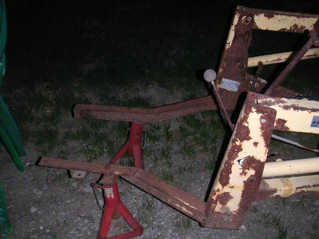
This is a photo of the L10 2nd type Loader Assembly: (Notice that it is disconnected from the subframe)
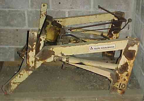
SubFrame (For L12 and L112 loaders):
This section lists and shows pictures of the L12 subframe parts used on the L10 2nd type, L12 and L112 Loaders.
The following major parts are needed:
1. Front Bracket
2. Left/Right Side Frame
3. LH Rear Mounting Bracket PN:2019159 and R.H. PN:2019158
4. Front Mount PN:2019804 and Capscrew 1/2" NF x 5" Grade 5 w/Nut
5. Wheel Spacer
6. Foot plate
7. Weight Box
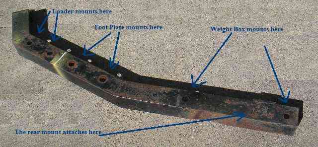
Front Bracket: (Three angles same bracket, this bracket seems to be the more difficult bracket to reproduce. It is the standard front steering plate, just wider and with ears on it. Looks a little more difficult inserting a bushing in the metal.)
L12 Loader Frame Mounting Sketch (angle bracket rear mounts):
Left Side Frame: (Angle 1 - upside down)
Left Side Frame: (Angle 2 - upside down, slightly different angle)
Left Side Frame: (Angle 3 - normal side up)
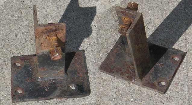
LH Rear Mounting Bracket(PN:2019159): (two angles of same bracket, R.H. is PN:2019158)
L12 - #20 Front Mount 2019804 and #19 Capscrew 1/2" NF x 5" Grade 5:
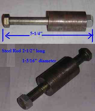
(Not sure if this is original)
Wheel Spacer and the spacers which allow for the tractor control bolt area:
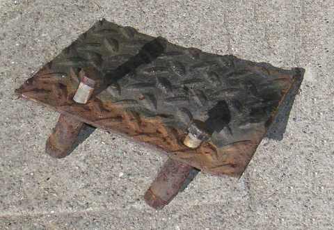
Foot plate: (Diamond plate steel)
The weight box:
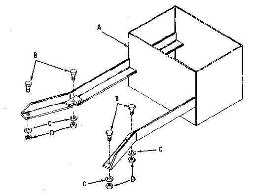
The sheet metal box is 9" deep on 3 sides and 6" on the front. 18 3/4" wide x 16" long. 2" angle iron each 40" long,piecut w/gussets 8" from end.
Page 9 - L12 manual showing wheel spacer installation
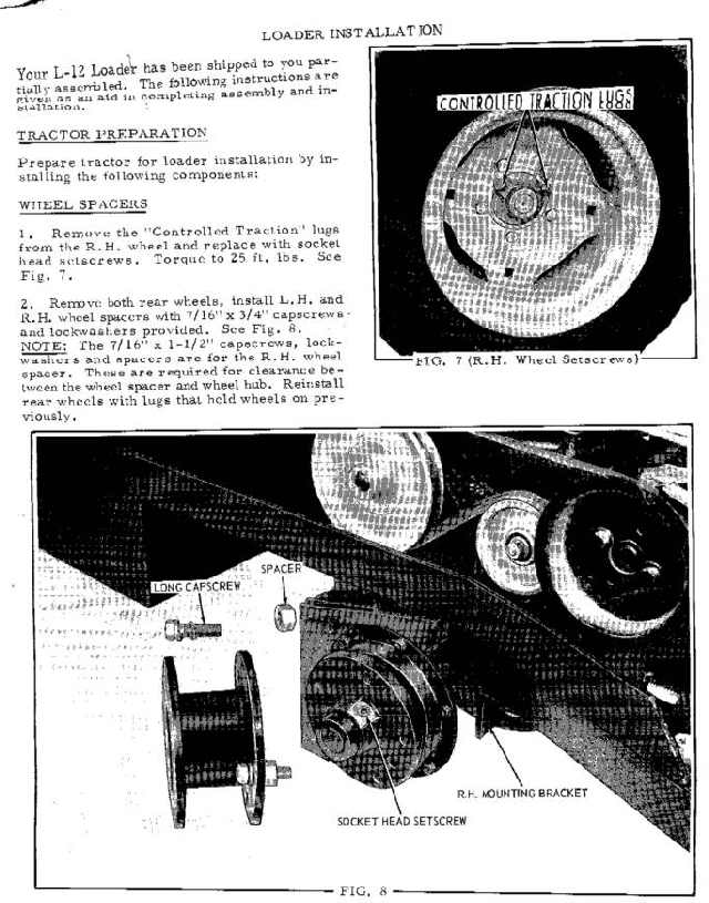
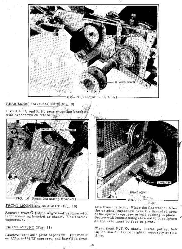
Page 10 - L12 manual showing wheel spacers, front mount and front mounting bracket
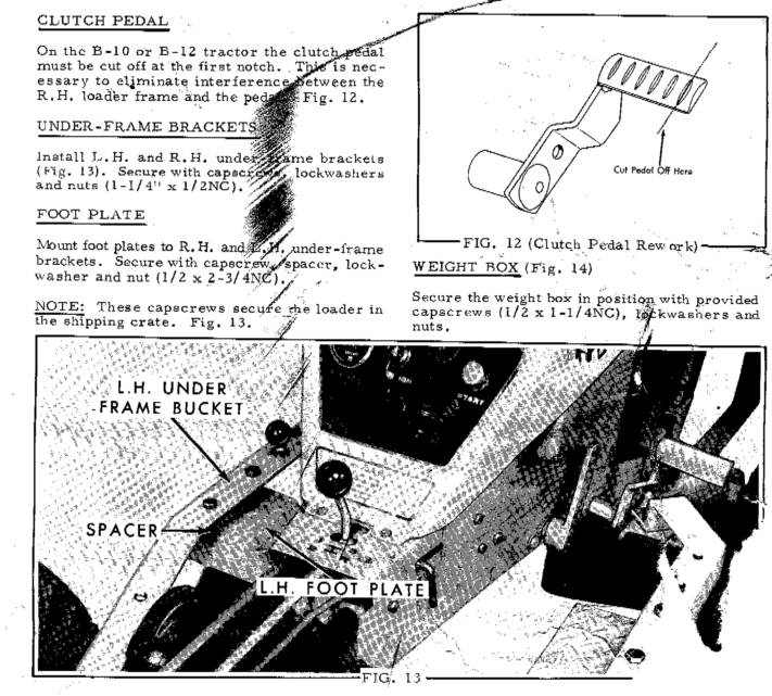
Page 11 - L12 manual showing foot plates and clutch pedal cut-off
Rear Mount for Long Frame Tractors:
The rear mount used on the long frame tractors (normally the 12hp machines, excluding the B12) used a round bar with attachment points. Below is a sketch of the mount.
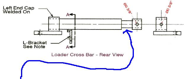
For detailed dimensions of the Long Frame tractor mount see the tip at the link below:
http://www.simpletractors.com/images/do_it/loader_bar_3000.jpg
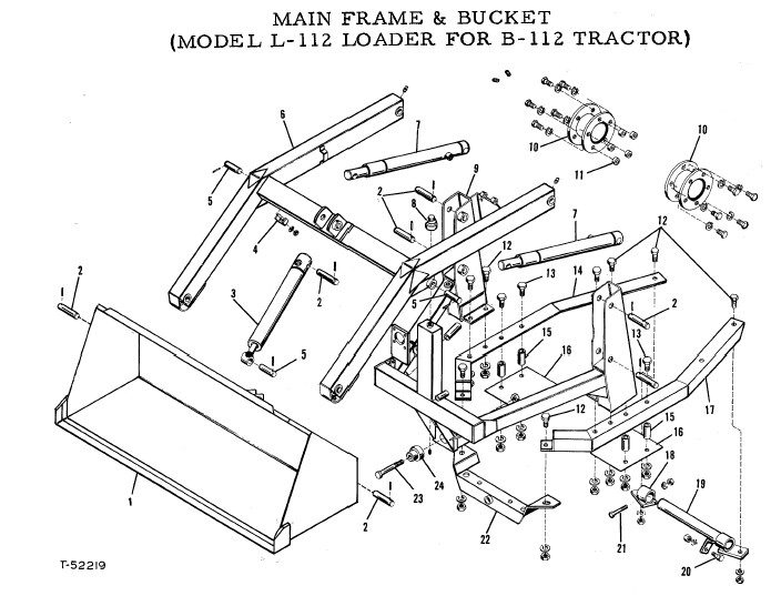
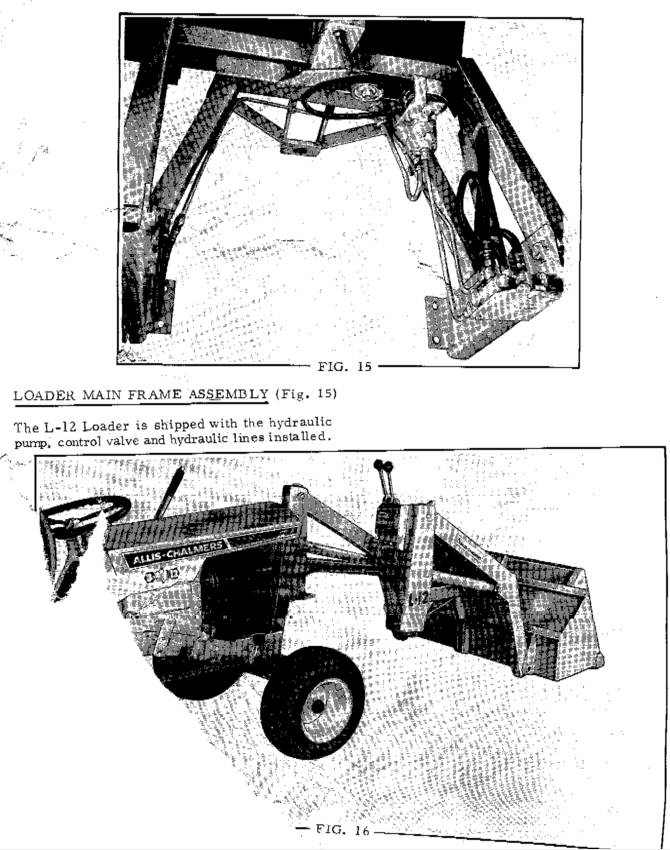
L12 Loader Assembly:
This section shows measurements and sketches of the L12 and L112 Loader Assembly.
Page 12 - L12 manual showing the loader main frame assembly
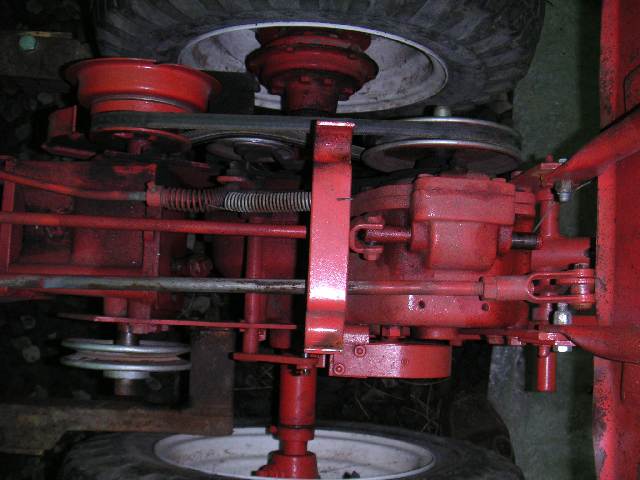
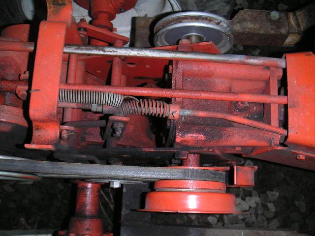
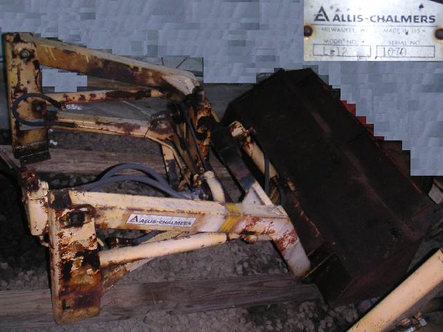
L12 Loader Assembly:
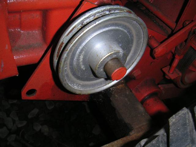
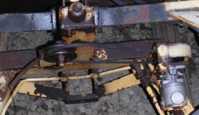
L12 Pullies and Hydraulic Pump
L10 1st type Serial Numbering:
The Henry Company made the L10 Loaders for Allis Chalmers. The manuals will refer to Henry Company part numbers.
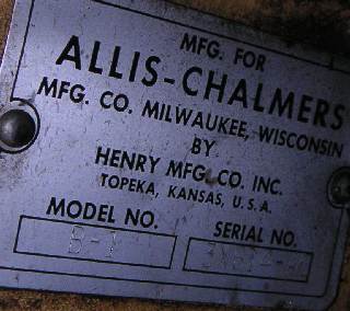
L10 Loader 1st type for the B1 Serial Number Plate (B1 3X614-AC):
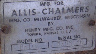
L10 Loader 1st type for the B10 Serial Number Plate:
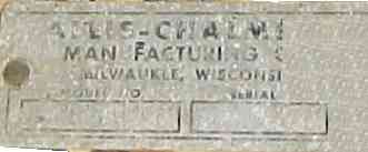
L10 2nd Type Serial Numbering
Below is the serial number plate from an L10 2nd type. Yes, the numbers are unreadable, but notice that the henry company did not take credit for the second type.
Quicktime movie of an L112 tractor:
YouYube Video:
Note: The following might be a substitute for the 1.5" wheel spacers on the early L10 Loader. Though there may be a problem with installing chains with only a 1.5" spacer. So the newer spacers may be better.
http://www.ezaccessory.com/5_Lug_Adapter_No_Pattern_Conversion_s/44.htm
Other articles referencing these loaders:
http://www.michaelstractors.com/forum/topic.asp?TOPIC_ID=1118
Bolts need to mount:
12 - 917270 (8) Capscrew 1/2" NC x 1-1/4" Grade 2
916966 1 Washer, Lock, 1/2"
916951 1 Nut, 1/2 NC
13 - 919984 (4) Capscrew, 1/2" NC x 2-3/4" Gr 2
916966 1 Washer, Lock, 1/2"
916951 1 Nut, 1/2 NC
Socket Head Set Screws 7/16"-20 needed for traction control bolts.
L12 Loader Belt is #30 in diagram: (has two numbers)
#30 V-Belt 2019808 - 32" 2065774
#30 V-Belt 2019363 - 2013556
Inside Diameter 29.8"
Outside Diameter 32"
Width 0.5"
|
")
