PTO Maintenance
The following sections are excerpts from the Simplicity Operators and Parts Manuals for the 3012/B112 Tractors. Note, that for years Simplicity never updated the manuals to show there are two styles of PTO's used on the 57-70 tractors; the PTO's are assembled differently. Some additional text, pictures and links to movies showing more detail will be added over time. (If you have pictures to contribute, please email or register and post them in a discussion - Thank you Michael)
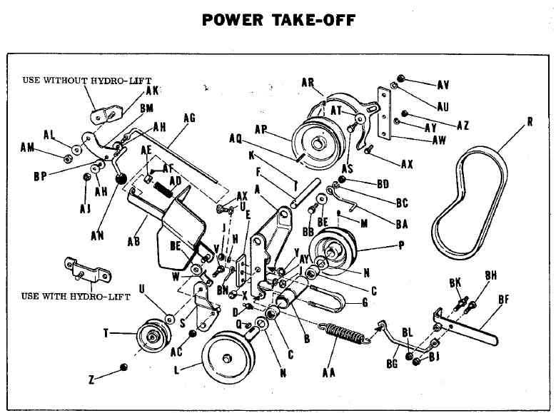
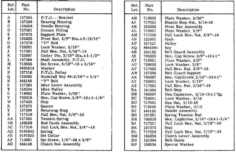
Power Take-Off Installation
For operation of Rotary Mower and Sickle Bar attachments, a power take-off attachment is required. This consists of the Power Take-Off Assembly, "V" Pulley for Bevel Gear Shaft, Drive Belt, Belt Guard, and Belt stop packaged in one carton.
For ease of attachment follow the steps outlined below:
1. Mount Drive Pulley to Shaft to Bevel Gear Assembly See Figure 15, and secure in place with Key and Set Screw. Hub of Drive Pulley is to face inward. Place Drive Belt (PTO Belt PN 164146 34"L x 1/2"W) on Drive Pulley and mount Belt Guard to inside surface of Side Plate nearest Drive Pulley. See Figure 19 for Mounting Bolt location. Attach the Belt Guard to the Guard Support as shown in figure 15. Allow approximately 3/16" clearance between Belt and Guard.
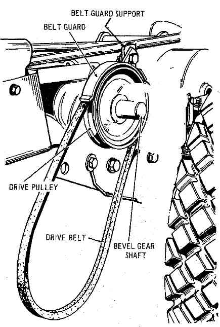
Figure 15
2. Holding the Power Take-Off Assembly in left hand as shown in Figure 16, position the tube of the Drive Bracket Assembly between the Bevel Gear Housing Side Plates. Align the holes in Side Plates with the hole in Drive Bracket Assembly Tube and insert Pivot Pin through holes in side Plates and Drive Bracket Assembly Tube.
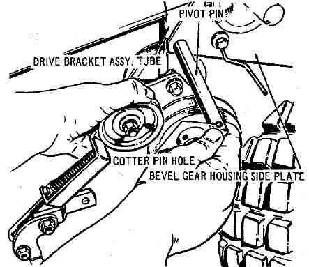
Figure 16
3. Push Pivot Pin through the holes in Bracket and Tube until the position of Cotter Pin is as shown in Figure 17. Secure in position with Cotter Pin furnished.
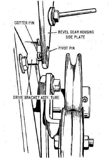
Figure 17
4. Remove Hex. Cap Screw "D" from frame of tractor and mount bracket in place on Lift Lever Quadrant. See Figure 18. Position the Pivot Bar Assembly flush against bottom of Lift Quadrant and re-install Hex. CapScrew and tighten securely. Check alignment of Drive Pulley on Bevel Gear Shaft, driven pulley of Power Take-Off, and Idler Pulley, and adjust Driving Pulley if necessary.
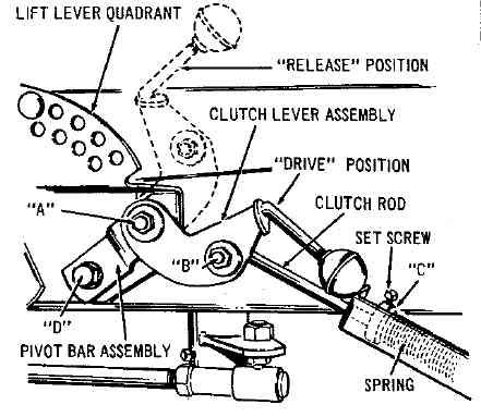
Figure 18
5. Remove Front Hex. Cap Screw from Pull Bar. Replace with stud 157273 provided. Short end inserted. Slip on Handle Assembly and tighten with Hex. HeadLock Nut to permit free movement of handle. Mount "V" Belt in place on driven pulley as shown in Figure 19 and attach spring to hole provided in the bottom of the Bracket ASsembly. Hook other end of the spring to the Handle Assembly. Mount Belt Stop as shown with 3/8" Bolt, Flat Washer, Lock-Washer. and Hex. Nut. When Implement is attached to tractor with Idler Pulley engaged, 1/8" clearance between Belt Stop and back of "V" Belt is required. Note: "V" Belt runs under Idler Pulley. See Figure 19.
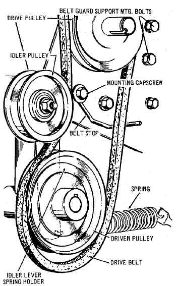
Figure 19
6. Figure 20, shows the tension handle.
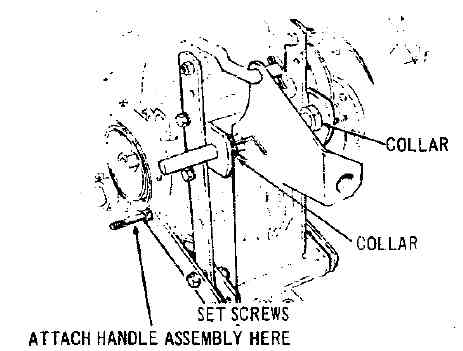
Figure 20
Operation
Operation of the Power Take-Off is controlled by movement of the Clutch Lever Assembly. See Figure 18. When the Clutch Lever is in the forward raised position, the Clutch Rod releases tension holding the Idler Pulley against the Drive Belt, and power will not be transmitted to the driven pulley of the Power Take-Off Assembly. When the Clutch Lever is in the back, depresesed position, the Clutch Rod applies tension to the Idler Pulley and as the Idler Pulley takes up th eslack in the Drive Belt, power is transmitted from the Drive Pulley on Bevel Gear Box Shaft to the driven pulley of the Power Take-Off. Figure 18 shows Clutch Lever in Drive position.
Adjustment
At points "A" and "B" of Figure 18, check tightness of Hex. Nut to be sure that Clutch Lever Assembly and Clutch Rod are free to pivot without binding.
Place Clutch Lever in "Drive" position and observe clearance between collar "C" (Figure 18) and end of bracket. When implement is attached to tractor, this clearance should normally be approximately 3/4"; at this setting the Idler Pulley should be snugly against the Drive Belt. If additional tenson is required, release Clutch Lever and loosen Set Screw on Collar and Slide Collar farther back on Clutch Rod. Retighten Set Screw in Collar and put Clutch Lever in Drive position. Recheck clearance. The tension of the Idler Pulley against the Drive Belt must be sufficient to operate whichever tractor attachment is being used. Any additional tension is unnecessary and will only cause premature failure of Belts and Idler Pulley bearings.
Lubrication
The Power Take-Off is lubricated by means of one Grease Fitting located on the bottom front of the Drive Bracket Assembly. Occasionally apply grease by means of a standard grease gun loaded with automotive type grease. Be sure to wipe dirt and grit from grease fitting before applying grease gun. Lubricate all pivot points and Idler Pulley Bearings with SAE 20 oil every few hours of operation.
Model 725 PTO:
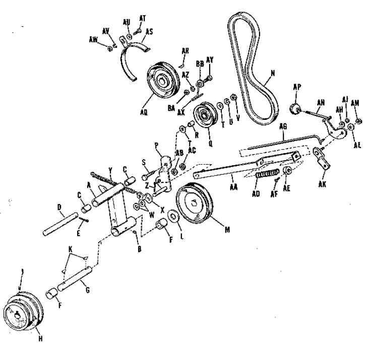
A 154228 Bracket Assembly, Drive
B 2727002 Fitting, Grease
C 2156064SM Bushing
D 2154233 Rod, Pivot
E 2722007 Pin, Cotter
F 2154258SM Bearing, Needle
G 154234 NLA-SEE 157118
H 154355 NLA-PULLEY-PTO
J 2713503 Screw, Set, Cup Point, Socket Hd., 5/16"-18 N.C. x 5/16" lg.
K 2725003 Key, Woodruff
L 2108182SM Washer
M 154308 NLA-PULLEY-05.00
N 2121078SM Belt, "V", Power Take-Off
P 154360 NLA-LEVER ASSY-I
Q 2154310 Pulley, Idler
R 2154177SM Bushing
S 2705016 Capscrew, Hex Hd., 3/8"-16 N.C. x 1-1/4" lg.
T 2719002 Washer, Plain, 5/16"
U 2720002 Washer, Lock, 3/8"
V 2717003 Nut, Hex, Full, 3/8"-16 N.C.
W 2719001 Washer, Plain, 3/8"
X 154368 NLA-CLIP-SPRING
Y 2154369SM Spring, Tension
Z 2722009 Pin, Cotter, 1/8" x 3/4" lg.
AA 154365 Guide Assembly, Rod
AB 2719001 Washer, Plain, 3/8"
AC 2717510 Nut, Lock, Hex Hd., Full, 3/8"-l6 N.C.
AD 1729277SM Spring
AE 1729276SM Collar, Set
AF 2713001 Screw, Set. Sq. Hd. Cup Pt., 1/4"-20 N.C. x 3/8" lg.
AG 2154364 Rod Assembly, Clutch
AH 2719002 Washer, Plain, 5/16"
AJ 2717511 Nut, Lock, Hex Hd., Full, 5/16"-18 N.C.
AK 154362 NLA-PIVOT BAR AS
AL 2719001 Washer, Plain, 3/8"
AM 2717510 Nut, Lock, Hex Hd. Full, 3/8"-16 N.C.
AN 154356 NLA-LEVER ASSY-C
AP 2122005SM Knob
AQ 154312 NLA-PULLEY-04.50
AR 2805850SM Key
AS 154243 NLA-GUARD ASSYBE
AT 2705005 Capscrew, 3/8"-16 N.C. x 1" lg.
AU 2719001 Washer, Plain, 3/8"
AV 2720002 Washer, Lock, 3/8"
AW 2717003 Nut, Hex, Full, 3/8"-16 N.C.
AX 8021014 NLA-STOP-BELT .1
AY 2705031 Capscrew, 3/8"-16 N.C. x 7/8" lg.
AZ 2720002 Washer, Lock, 3/8"
BA 2717003 Nut, Full, Hex, 3/8"-16 N.C.
BB 2719001 Washer, Plain, 3/8"
Some discussions about the PTO:
PTO questions
Questions about PTO
PTO Belt Sizes |
")

